I was delayed considerably by the 4 days of power loss from MD and VA's huge storm last week.
Anyway, a couple weeks ago I received the PCB for the electret preamp PCB. I ordered it from Elliot Sound Products and considering it was shipped from Australia it arrived as soon as expected.
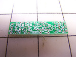
Here's the PCB:
The grid in the photo is an inch square, yes it's really that small. I ordered all the parts I needed for it from Digikey. Though I had to reorder a couple part as they were too big for the PCB.
Here's the finished PCB with XLR jack and Electret capsule attached:
I replaced the panel mount XLR with an inline connector so I could plug it directly into my Zoom H4n. Also notice the 2 capacitors mounted under the PCB, they arrived a little too big for the PCB, so I managed to mount them upside-down, making sure the polarity was correct of course.
So while I was waiting for the PCB to arrive I did some tests with working with the steel conduit. I don't have any pictures, but needless to say working with steel is a whole lot of trouble. I decided for the sake of time and my sanity I would work with PVC. I've got a whole lot more experience working with PVC, namely the 3 Pneumatic spud guns I built in high school.
After constructing the PCB, I did a couple test recordings with the electret capsule placed just inside PVC and Brass tubes, just to see what they sounded like.
Here's an image of what they sounded like:
I've labeled the spectrograph with where I spoke "On-Axis" and "90 degrees off axis" You can see there's a little bit of high frequency attenuation on the 90 deg. an the on-axis is far more full spectrum. But there is the issue of the harmonics generated by the solid tube.
The same properties exist with the Brass tube, but the harmonics are far more harsh, both examples would be useless for recording anything useful.
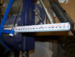
So for my first PVC prototype I started by cutting slots into the PVC pipe. I tried using my Dad's scroll saw, but I wasn't able to maintain a consistent cut. So instead I used the good ole' trusty hack saw:
I cut parrallel slots along both sides of the pipe, but after finishing, I discovered a structural issue with using PVC. All those slots made the PVC extremely bendy, I'll have to address the issue in the future. I went ahead and tried recording the pickup pattern of the pipe as it was.
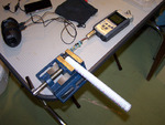
Here was my setup:
I simply stuck the capsule inside the tube, far enough up that the capsule was just in front of the last few slots, that way the rejection holes on the back the capsule would get used.
Here's the spectrograph of the results:
This time I used white noise generated from my ipod touch, which gave a far more quantifiable result.
On-Axis was pretty much as expected, however there is a nasty resonance to the tube, right around 2.4 khz. As we move to 45 deg off-axis, the high frequencies attenuate slightly, and more so at 90. 135 deg off-axis was the most attenuated, and I think 180 was louder because the back of the tube was not block off, I fixed this issue in later tests. Ultimately though, the tube still hade nasty harmonic resonance, and the attenuation was hardly noticeable.
After that I finished the prototype as I had intended, by cutting out every other hack saw slot to create larger slots.
Here's what it looks like, as well as the current configuration of the preamp PCB:
The PVC is even more flimsy in this configuration.
Here's the spectrograph of the test measurement with white noise:
Overall the graph is pretty much the same as the previous test, other than that the 180 off-axis is further attenuated by the foam I stuffed in the tube behind the capsule.
My next (and current) prototype leads me into attempting to cite a Patent for the first time:
Shingo Suzuki. (March 25th, 2010) Narrow Directional Microphone. US Patent: US 2010/0260369 A1
Hopefully that covers everything, here's a link to the patent on Google Patents: http://www.google.com/patents?id=MFPXAAAAEBAJ
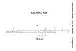
So while researching interference tubes, I read several patents on said interference tubes in order to gleam some insight into this technology. This particular one, a far more recent patent has a couple diagrams that caught my eye:
 This is described as: "FIG 8 is a cross-sectional view of a conventional narrow directional micropone..." (paragraph 0020)
The patent itself is for a new method of creating shotgun mics, by using a "accoustic resistor" membrain between the two layers in the diagram above. The membrain attenuated the signal by forcing it to transfer from air to the membrain back to air again inside the tube. I have seen this used in several shotgun mics I've used at school, but it's far too advanced of a production technique to attempt in my workshop. So for now I'm going to attempt to recreate this "conventional" microphone with PVC.
It just so happens that 1/2" PVC nests quite nicely into 3/4" PVC, so I'm going to cut incresingly smaller slots parrallel with the tube into the 1/2" PVC, and a set of perpendicular slots in the 3/4" PVC. These slots cut in perpenicular of each other should stiffen up both PVC tubes when thier nested together.
I've already cut the internal tube, and I'm currently working on the outer tube, I'll update again when I've finished it and measured the results.


